
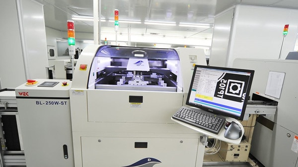
PCB
あなたのプロジェクトはリジッドPCBAまたはフレックスに適していますか
- Electronic PCB Factories
さまざまな Web サイトで「PCBA」という言葉を目にするとき、より厳密な PCBA の概念を表しています。 ただし、PCBA は、リジッド ボード、フレキシブル ボード、さらには HID PCB の両方を指す場合があります。 電子製品の小型化のますます明白な特徴に直面して、FS Technology フレキシブル PCBA は、成形、曲げ、ねじれ、折り畳みが可能であり、電子プロジェクトの無限の可能性を実現するため、大きな人気を得ています。 最終的な目的として、リジッド、フレキシブル、またはリジッド フレックス PCBA のいずれであっても、それらは電子製品に同じ効果をもたらします。つまり、さまざまな電気部品と機械部品を接続します。 エレクトロニクス プロジェクトに使用するボードの種類を知るには、それらが作成される手順を理解する必要があります。
リジッド基板とフレキシブル基板の使い分け方
電子プロジェクトのコストに関しては、リジッド PCBA の価格は通常、フレキシブル回路基板の価格よりも低くなります。 FS Technologies が「通常」と呼ぶのは、PCBA のコストを構成するすべての要因が同じ場合です。 リジッド PCBA よりもフレックス ボードを使用する方が安価な場合があります。 ターンキー アセンブリの総所有コストを正確に把握するには、考慮すべき要素が多数あります: PCBA分析費用。 フレキシブル回路により、コネクタ、ワイヤ ハーネス、その他の回路基板などのコンポーネントが不要になります。 これらのコンポーネントを設計から削除することで、材料費、人件費、組み立て費、スクラップ コストが削減されます。
ラップトップとデスクトップ コンピューター、オーディオ キーボード、ソリッド ステート ドライブ、フラット パネル TV とモニター、子供のおもちゃ、その他の私たちの生活で使用されるデバイスは、通常、信頼性の要件を満たすために、柔軟なボードの代わりに FS テクノロジのリジッド ボードを使用します。 しかし、フレキシブル PCBA の価値が低いとは思わないでください。GPS ユニット、タブレット、スマートフォン、カメラ、ウェアラブル デバイスで広く使用されています。
より複雑な回路の場合、柔軟な PCBA を選択するのが最も賢明な選択です。 その 3 次元空間の制御は、他のどのタイプの PCB にも匹敵しません。 もちろん、これはローテクアプリケーションでの使用には影響しません。 ショッピングモールのカウンターのLED照明にはフレキシブル基板が使われており、設置が容易になるケースもあります。
リジッドPCBAとフレックス回路の類似点と相違点
リジッド PCBA プロジェクトを設計する場合、FS Technology は、最小穴サイズ、最小スペースとトレース幅、ボード エッジまでの最小距離、銅および全体の設計厚さなど、必要な特定の設計規則に従います。 リジッド回路とフレキシブル回路の設計要件には、実際には多くの共通点があります。 これらの一般的なプロセスは次のとおりです。
- 穴あけ・貫通穴加工
- メッキ
- 光学イメージングと開発
- 銅トレース、パッド、輪郭、およびプレーンのエッチング
- ベーキングにより、PCB から水分を除去します。
フレキシブル回路オーバーレイ
中国で最もプロフェッショナルなターンキー PCBA アセンブリ会社である FS Technology は、回路オーバーレイまたはオーバーレイ プロセスを使用して、フレキシブル回路の外部回路をカプセル化および保護します。 フレックス回路のカバー フィルリジッド基板 のはんだマスクに似ていますが、1 つの本質があります。それは、カバー フィルムの方が柔軟性が高いということです。 fs-pcba.com によると、「カバー フィルムは通常、熱硬化性接着剤でコーティングされたポリイミド フィルムです。フィルムの厚さは .0005 インチから .005 インチの範囲で、.001 インチと .002 インチが最も一般的です。
ポリイミドと接着剤のオーバーレイは、圧力と熱を使用してラミネート加工されます。熱によって接着剤が流れやすくなり、トレースとパッドの間のギャップが埋められます。 これにより、層の間に空気が閉じ込められるのを防ぎます。 再び fs-pcba.com.ja から: 「接着剤の流れは、完全な表面接触とカプセル化を確実にするために必要です。接着剤は、下の画像に示されている開口部の周りでわずかににじむ傾向があります。このブリード押し出しは、しばしば「バインダー押し出し」と呼ばれます。 」であり、実際には理想的な現象です。
オーバーレイ積層プロセスが完了したら、ドリル、ルーティング、またはレーザー切断を使用して、コンポーネントおよび/または機能の開口部を作成します。 エッチングは使用できません。
リジッドおよびフレキシブル PCB の IPC 規格
IPC-2221A、プリント基板設計の一般規格
IPC-2223、フレキシブル プリント基板の分割設計に関する規格
IPC-4101、リジッドおよび多層プリント基板用基材の仕様
IPC-4202、フレキシブル プリント回路用フレキシブル ベース誘電体
IPC-4203、フレキシブル プリント回路のカバーおよびフレキシブル接着剤接合フィルムとして使用するための接着剤コーティング誘電体フィルム
IPC-4204、フレキシブル プリント回路の製造のためのフレキシブル メタル クラッド誘電体
IPC-6013、フレキシブル プリント回路の認定および性能仕様
リジッド基板とフレキシブル基板のまとめ
リジッド PCBA とフレキシブル PCBA は電子製品に同じ影響を与えますが、電子部品をリンクする役割しか果たしませんが、回路基板は依然として電子製造の重要な部分です。 ほとんどのエンジニアは同じエレクトロニクス プロジェクトにリジッド PCB とフレックス PCB を使用しますが、フレックス PCBA には追加の製造プロセス ステップがあるため、いくつかの特別な規則が必要です。 リジッド PCBA は低コストのように見えますが、回路基板の価格を評価する前に、1 枚の基板のコストではなく総コストを考慮する必要があります。
What are the circuit board repair steps-FS Technology
- Electronic PCB Factories
Summary: In recent years, the management level of industrial equipment has improved significantly, so the number of industrial control boards in several industries has also increased. After the collapse of the regulatory industry, the cost of replacing equipment has also become a major headache for entrepreneurs. So do you know how to fix a circular screen? What are the steps to fix the round screen? Next, let's take a look at the knowledge of circuit board maintenance with FS Tech.
Look first, measure later
FS Technology recommends that you should check the navigation screen. If necessary, pay attention to the magnifying glass.
Mainly see:
1. Whether the cable is broken or short-circuited, especially the connecting wire printed on the round screen is broken or stuck.
2. Whether there are suitable components such as resistors, capacitors, inductors, diodes, triodes, etc. It was interrupted.
3. Is there any maintenance? Which parts were pressed? There are problems with welding, welding, improper installation, etc.

Inside out
When testing with a series switch, it is best to use a standard switch similar to the suggested design, if possible. Then use the VI Folding Bar function to make a negative comparison of the two plates. The test points start from the peripheral ports, and then from the outside to the inside, especially the capacitance comparison test. This covers losses when it is difficult to determine if the multimeter is leaking.
Easy before difficult
In order to improve the FS technology test results, some technical processing of the modified screen is required to interfere with the various interference factor tests before the online circuit board test. The specific conditions are:
1. Preparation before the test
Short circuit crossover oscillator circuit for high voltage power supply to open footwell. The charging and discharging of large capacitors can also cause interference.
2. Use the exclusion method to test the device
In online or similar device testing, for each device that passes the test (or abnormality), the test results are directly checked and recorded. If the test fails (or fails), it will be retried. If it still fails, FS Technology recommends that you check the test results first. This continues until the device is tested (or compared to the screen). Then deal with those devices that fail the test (or are impatient).

3. Use the ASA-VI curve scan test to compare and test the devices not covered by the test library
ASA-VI Smart Folding technology can be used for similar testing as any other device. While testing procedures may include equipment, there is a table to consider. Through comparative testing, the device has a high error rate and can detect errors. When testing your device over the web, this feature goes beyond the limitations of library testing devices and expands the selection of navigational agency failure detection devices.
static before moving
Currently, the functionality on the navigation screen may be limited to analyzing the navigation and characteristics of the device on the navigation screen. Therefore, if a defective board is manufactured, it must be placed on the first test equipment. For best results in this inspection job, judge whether the circle chart is appropriate. At this point, it's a good idea to check that the device's power is properly connected to the navigation screen, and that the connectors on the screen are connected. Make sure the influence of the circle context and the circle error are isolated, otherwise the correct action will be taken!