Main functions and common faults of stepper motor encoders
1. Basic definition and function of stepper motor encoders
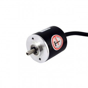
Stepper motor encoders are sensors attached to stepper motors, mainly used to monitor the mechanical angle or linear displacement of the motor in real time, and convert it into electronic signals to feed back to the control system (such as PLC). This feedback mechanism can make up for the shortcomings of stepper motor open-loop control, solve problems such as step loss and step loss, and improve positioning accuracy and dynamic response performance.
2. Specific working principle of stepper motor encoders
1. Grating disk: engraved with equally spaced light-transmitting grooves, which rotates as the motor rotates.
2. Photoelectric sensor: includes LED light source and photosensitive receiver (such as phototransistor), which is used to detect changes in light and generate electrical signals.
3. Signal generation: When the motor rotates, the grating disk rotates, the light is periodically blocked, and the photoelectric sensor outputs a pulse signal (A phase and B phase). There is a 90° phase difference between the two phase signals, which is used to determine the direction of rotation. In addition, there is a Z phase signal, which outputs a pulse for each rotation for position calibration.
3. Main functions of stepper motor encoders
1. Improve accuracy: The encoder can feed back the actual position information of the motor to the controller, so that the controller can compare and calculate according to the preset target position and the actual position, and output a more accurate control signal to drive the motor. This can avoid the problem of inaccurate positioning caused by error accumulation and improve the running accuracy of the motor.
2. Improve stability: Through the feedback of the encoder, the controller can monitor the running status of the motor in real time, such as speed, torque and other parameters. When the motor is abnormal, the controller can take timely measures, such as reducing the speed, stopping operation, etc., to protect the motor from damage, thereby improving the stability of the system.
3. Achieve precise control: The position feedback information provided by the encoder enables the controller to adjust the control strategy according to the actual situation, such as adopting a more sophisticated speed regulation algorithm, or to achieve more complex control tasks, such as trajectory tracking, positioning, etc. This is very important for application scenarios that require high precision and fast response.
4. Feedback and calibration: The encoder compares the actual position of the motor with the expected position, thereby achieving precise positioning and control of the motor. This helps to improve the stability and accuracy of the system.
5. Speed detection: The speed of the motor can be calculated by the pulse frequency measured by the encoder. This is very important for monitoring and controlling the running speed of the motor.
6. Torque control: In some applications, the output torque of the motor can be changed by adjusting the input signal of the encoder. For example, in robot control, the torque of the motor can be adjusted according to the task requirements to achieve precise operation.
7. Prevent overshoot and undershoot: The encoder provides the actual speed information of the motor. The controller can effectively adjust the operation of the motor based on this information to avoid overshoot or undershoot during the operation of the motor, thereby improving the operating performance of the system.
8. Realize closed-loop control: The encoder is used in combination with the motor to achieve closed-loop control of the motor. This control method can improve the response speed, stability and accuracy of the system, so that the system can maintain stable operation in various complex environments.
4. Common faults of stepper motor encoders
1. Unstable signal: This is one of the most common faults of the encoder, which may be caused by poor cable connection, power supply fluctuations or electromagnetic interference. Solutions include checking whether the cable connection is firm, ensuring stable power supply, and taking appropriate electromagnetic shielding measures.
2. Zero offset: The encoder output signal is inaccurate at the initial position, which may be due to loose mechanical installation, external impact or wear caused by long-term use. The solution includes recalibrating the encoder and checking whether the mechanical installation is firm.
3. Output signal loss: It may be caused by damage to the internal components of the encoder, power failure or line short circuit. The solution includes checking whether the power supply is normal, and checking the circuit and internal components of the encoder.
4. Resolution reduction: It may be caused by grating contamination, aging of optical components or failure of electronic components. The solution includes cleaning and maintaining the encoder, and replacing damaged optical or electronic components if necessary.
5. Overheating: Excessive ambient temperature, poor heat dissipation or internal circuit short circuit may cause the encoder to overheat, thereby reducing its performance or even damaging it. The solution includes ensuring that the working environment temperature of the encoder is suitable, strengthening heat dissipation measures, and checking whether the internal circuit is abnormal.
6. Connection cable failure: The encoder connection cable is broken, short-circuited or poorly contacted. It is a common problem. The solution includes replacing the cable or connector and ensuring that the cable is fixed and tightened.
7. Low power supply voltage: Low power supply voltage will affect the normal operation of the encoder. Solutions include repairing the power supply or replacing the cable.
8. Mechanical component failure: Shaft wear or breakage, bearing damage, etc. will affect the rotation accuracy of the encoder and the accuracy of the measured data. Solutions include regular inspection and maintenance of mechanical components.
9. Communication failure: Interface mismatch, communication protocol error, or line failure may cause data transmission errors. Solutions include ensuring that the interface matches, the communication protocol is correct, and checking whether the communication line is unobstructed.