How to control the CNC spindle motor?
1. Definition of CNC spindle motor
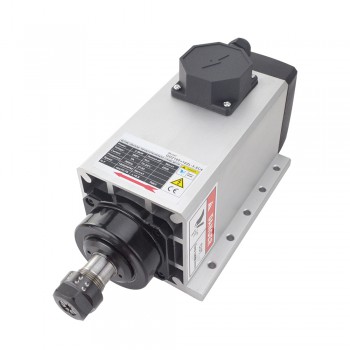
A CNC spindle motor is a critical component in a CNC machine, the main function of the spindle motor is to drive the spindle of the mechanical equipment to rotate, so as to complete tasks such as processing and cutting. Its performance directly affects the processing accuracy, efficiency and stability of the equipment.
2. Working principle of CNC spindle motor
The operation of the CNC spindle motor is based on the principle of electromagnetic induction. When AC is applied to the three-phase winding, a rotating magnetic field is generated in the stator. This rotating magnetic field cuts the rotor conductor, thereby generating an induced current in the rotor conductor. The induced current interacts with the rotating magnetic field to generate an electromagnetic force that drives the rotor to rotate. There is a certain difference between the speed of the rotor and the speed of the rotating magnetic field. This difference is called the slip. By controlling the slip, the spindle motor speed can be precisely controlled.
3.Components of CNC spindle motor
1. Stator:The stator is the stationary part of the motor and houses the windings. It is responsible for generating the magnetic field that interacts with the rotor.
2. Rotor:The rotor is the rotating part of the spindle motor. It is driven by the magnetic field created by the stator. The rotor is connected to the spindle shaft, which directly drives the cutting tool.
3. Bearings:Bearings support the spindle and allow it to rotate with minimal friction. High-quality bearings are crucial to ensure that the spindle motor operates smoothly and accurately, as they help to reduce vibrations and ensure precision during operation.
4. Spindle Shaft:The spindle shaft is the central part that connects the rotor to the tool being used in the machining process.
5. Cooling System:Cooling systems are vital to keep the spindle motor temperature within safe operating limits, especially during high-speed operation.
6. Encoder:The encoder provides feedback on the position and speed of the spindle motor. It allows the CNC system to accurately control the motor's speed and positioning by sending signals about the rotor's movement to the machine's control system.
7. Drive System:The drive system consists of components that convert electrical energy into mechanical energy to rotate the spindle. It includes components like the motor controller, inverter, and drive circuitry.
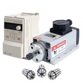
8. VFD (Variable Frequency Drive):The VFD is used to control the motor's speed by adjusting the frequency of the electrical supply.
9. Cooling Fan:A cooling fan (or ventilation system) is sometimes incorporated into the motor assembly to provide active air cooling.
10. Housing:The housing is the outer casing of the spindle motor that protects the internal components, such as the stator, rotor, and bearings, from dirt, debris, and damage.
11. Electrical Connections:These are the wiring and connectors that supply power to the motor and interface with the CNC controller and other components.
12. Feedback System:Some advanced spindle motors include additional feedback systems, such as tachometers or resolvers, which provide more precise information on motor speed and position.
4.The control modes of CNC spindle motor
1. Constant Speed Control Mode:In this mode, the spindle motor runs at a fixed, constant speed throughout the machining process.It is used for operations where the tool does not need to change its speed dynamically during the process.
2. Constant Torque Control Mode:This mode adjusts the motor’s speed to maintain a constant torque throughout the operation, ensuring the motor delivers consistent cutting force.This is ideal for machining operations where the cutting load varies but the motor's torque needs to remain steady to prevent tool stalling.
3. Vector Control (Field-Oriented Control, FOC) Mode:Vector control provides high precision and dynamic control of the motor by controlling the magnetic field inside the motor. It adjusts both the torque and speed based on real-time demands.This mode is particularly useful in high-performance CNC systems, providing smoother operation, better acceleration/deceleration, and high-speed control.
4. Closed-Loop Control Mode:Closed-loop control involves a feedback system where the motor speed, torque, and position are continuously monitored, and adjustments are made in real-time to keep the system running optimally.Feedback devices like encoders or resolvers help achieve high precision and accuracy by adjusting motor parameters to ensure the desired output is achieved.
5. Open-Loop Control Mode:In open-loop control, there is no feedback mechanism to adjust the motor’s operation based on real-time performance.The motor is controlled based on pre-set parameters, such as speed or power, without ongoing monitoring or adjustments.
6. Synchronous Motor Control:Synchronous motors operate at a fixed speed, determined by the frequency of the electrical supply.These motors are typically used when precise speed control is required, as they run at a constant speed without fluctuating under load.
7. Dynamic Brake Control Mode:Dynamic braking is often used for rapid deceleration of the spindle motor after the machining process is completed.This method uses the motor itself to dissipate the kinetic energy, slowing down the motor quickly by converting it into heat.
8. Speed and Torque Control Mode (Dual Mode):This control mode combines both speed and torque control to give the spindle motor the ability to adjust both parameters simultaneously.
Source:https://www.tumblr.com/raysteppermotor/780975432515420160/how-to-control-the-cnc-spindle-motor
A CNC spindle motor is a critical component in a CNC machine, the main function of the spindle motor is to drive the spindle of the mechanical equipment to rotate, so as to complete tasks such as processing and cutting. Its performance directly affects the processing accuracy, efficiency and stability of the equipment.
2. Working principle of CNC spindle motor
The operation of the CNC spindle motor is based on the principle of electromagnetic induction. When AC is applied to the three-phase winding, a rotating magnetic field is generated in the stator. This rotating magnetic field cuts the rotor conductor, thereby generating an induced current in the rotor conductor. The induced current interacts with the rotating magnetic field to generate an electromagnetic force that drives the rotor to rotate. There is a certain difference between the speed of the rotor and the speed of the rotating magnetic field. This difference is called the slip. By controlling the slip, the spindle motor speed can be precisely controlled.
3.Components of CNC spindle motor
1. Stator:The stator is the stationary part of the motor and houses the windings. It is responsible for generating the magnetic field that interacts with the rotor.
2. Rotor:The rotor is the rotating part of the spindle motor. It is driven by the magnetic field created by the stator. The rotor is connected to the spindle shaft, which directly drives the cutting tool.
3. Bearings:Bearings support the spindle and allow it to rotate with minimal friction. High-quality bearings are crucial to ensure that the spindle motor operates smoothly and accurately, as they help to reduce vibrations and ensure precision during operation.
4. Spindle Shaft:The spindle shaft is the central part that connects the rotor to the tool being used in the machining process.
5. Cooling System:Cooling systems are vital to keep the spindle motor temperature within safe operating limits, especially during high-speed operation.
6. Encoder:The encoder provides feedback on the position and speed of the spindle motor. It allows the CNC system to accurately control the motor's speed and positioning by sending signals about the rotor's movement to the machine's control system.
7. Drive System:The drive system consists of components that convert electrical energy into mechanical energy to rotate the spindle. It includes components like the motor controller, inverter, and drive circuitry.
8. VFD (Variable Frequency Drive):The VFD is used to control the motor's speed by adjusting the frequency of the electrical supply.
9. Cooling Fan:A cooling fan (or ventilation system) is sometimes incorporated into the motor assembly to provide active air cooling.
10. Housing:The housing is the outer casing of the spindle motor that protects the internal components, such as the stator, rotor, and bearings, from dirt, debris, and damage.
11. Electrical Connections:These are the wiring and connectors that supply power to the motor and interface with the CNC controller and other components.
12. Feedback System:Some advanced spindle motors include additional feedback systems, such as tachometers or resolvers, which provide more precise information on motor speed and position.
4.The control modes of CNC spindle motor
1. Constant Speed Control Mode:In this mode, the spindle motor runs at a fixed, constant speed throughout the machining process.It is used for operations where the tool does not need to change its speed dynamically during the process.
2. Constant Torque Control Mode:This mode adjusts the motor’s speed to maintain a constant torque throughout the operation, ensuring the motor delivers consistent cutting force.This is ideal for machining operations where the cutting load varies but the motor's torque needs to remain steady to prevent tool stalling.
3. Vector Control (Field-Oriented Control, FOC) Mode:Vector control provides high precision and dynamic control of the motor by controlling the magnetic field inside the motor. It adjusts both the torque and speed based on real-time demands.This mode is particularly useful in high-performance CNC systems, providing smoother operation, better acceleration/deceleration, and high-speed control.
4. Closed-Loop Control Mode:Closed-loop control involves a feedback system where the motor speed, torque, and position are continuously monitored, and adjustments are made in real-time to keep the system running optimally.Feedback devices like encoders or resolvers help achieve high precision and accuracy by adjusting motor parameters to ensure the desired output is achieved.
5. Open-Loop Control Mode:In open-loop control, there is no feedback mechanism to adjust the motor’s operation based on real-time performance.The motor is controlled based on pre-set parameters, such as speed or power, without ongoing monitoring or adjustments.
6. Synchronous Motor Control:Synchronous motors operate at a fixed speed, determined by the frequency of the electrical supply.These motors are typically used when precise speed control is required, as they run at a constant speed without fluctuating under load.
7. Dynamic Brake Control Mode:Dynamic braking is often used for rapid deceleration of the spindle motor after the machining process is completed.This method uses the motor itself to dissipate the kinetic energy, slowing down the motor quickly by converting it into heat.
8. Speed and Torque Control Mode (Dual Mode):This control mode combines both speed and torque control to give the spindle motor the ability to adjust both parameters simultaneously.
Source:https://www.tumblr.com/raysteppermotor/780975432515420160/how-to-control-the-cnc-spindle-motor